| www.play-hookey.com | Sun, 08-24-2003 | |
| Digital | Logic Families | Digital Experiments | Analog | Analog Experiments | DC Electronic Theory | Optics | Computers | Semiconductors | Test HTML | ||
| Direct links to other pages: | |
|---|---|
| Basic Summing: | [Setting the Gain Coefficient] [Analog Addition] [Adding a Fixed Constant] |
| Variations in Feedback Circuits: | [Integrators] [Differentiators] [Logarithmic Amplifiers] [Non-Inverting Amplifiers] [A Difference Amplifier] [Increasing the Output Current Capacity] [A Half-Wave Rectifier] [A Full-Wave Rectifier] |
| Mixing Analog and Digital Technologies: | [Comparators] [Digital to Analog Conversion] [Analog to Digital Conversion] |
| Generating Waveforms: | [A Square Wave Generator] [A Triangle Wave Generator] [A Sine Wave Generator] |
| Operational Amplifiers: | [Characteristics of Operational Amplifiers] [Inside the 741] |
| Digital to Analog Conversion |
|---|
One common requirement in electronics is to convert signals back and forth between analog and digital forms. Most such conversions are ultimately based on a digital-to-analog converter circuit. Therefore, it is worth exploring just how we can convert a digital number that represents a voltage value into an actual analog voltage.
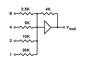
The circuit to the right is a basic digital-to-analog (D to A) converter. It assumes a 4-bit binary number in Binary-Coded Decimal (BCD) format, using +5 volts as a logic 1 and 0 volts as a logic 0. It will convert the applied BCD number to a matching (inverted) output voltage. The digits 1, 2, 4, and 8 refer to the relative weights assigned to each input. Thus, 1 is the Least Significant Bit (LSB) of the input binary number, and 8 is the Most Significant Bit (MSB).
If the input voltages are accurately 0 and +5 volts, then the "1" input will cause an output voltage of -5 × (4k/20k) = -5 × (1/5) = -1 volt whenever it is a logic 1. Similarly, the "2," "4," and "8" inputs will control output voltages of -2, -4, and -8 volts, respectively. As a result, the output voltage will take on one of 10 specific voltages, in accordance with the input BCD code.
Unfortunately, there are several practical problems with this circuit. First, most digital logic gates do not accurately produce 0 and +5 volts at their outputs. Therefore, the resulting analog voltages will be close, but not really accurate. In addition, the different input resistors will load the digital circuit outputs differently, which will almost certainly result in different voltages being applied to the summer inputs.
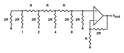
The circuit above performs D to A conversion a little differently. Typically the inputs are driven by CMOS gates, which have low but equal resistance for both logic 0 and logic 1. Also, if we use the same logic levels, CMOS gates really do provide +5 and 0 volts for their logic levels.
The input circuit is a remarkable design, known as an R-2R ladder network. It has several advantages over the basic summer circuit we saw first:
One detail about this circuit: Even if the input ladder is extended, the output will remain within the same output voltage limits. Additional input bits will simply allow the output to be subdivided into smaller increments for finer resolution. This is equivalent to adding inputs with ever-larger resistance values (doubling the resistance value for each bit), but still using the same two resistance values in the extended ladder.
The basic theory of the R-2R ladder network is actually quite simple. Current flowing through any input resistor (2R) encounters two possible paths at the far end. The effective resistances of both paths are the same (also 2R), so the incoming current splits equally along both paths. The half-current that flows back towards lower orders of magnitude does not reach the op amp, and therefore has no effect on the output voltage. The half that takes the path towards the op amp along the ladder can affect the output.
The most significant bit (marked "8" in the figure) sends half of its current toward the op amp, so that half of the input current flows through that final 2R resistance and generates a voltage drop across it. This voltage drop (from bit "8" only) will be one-third of the logic 1 voltage level, or 5/3 = 1.667 volts. This is amplified by the op amp, as controlled by the feedback and input resistors connected to the "-" input. For the components shown, this gain will be 3 (see the page on non-inverting amplifiers). With a gain of 3, the amplifier output voltage for the "8" input will be 5/3 × 3 = 5 volts.
The current from the "4" input will split in half in the same way. Then, the half going towards the op amp will encounter the junction from the "8" input. Again, this current "sees" two equal-resistance paths of 2R each, so it will split in half again. Thus, only a quarter of the current from the "4" will reach the op amp. Similarly, only 1/8 of the current from the "2" input will reach the op amp and be counted. This continues backwards for as many inputs as there are on the R-2R ladder structure.
The maximum output voltage from this circuit will be one step of the least significant bit below 10 volts. Thus, an 8-bit ladder can produce output voltages up to 9.961 volts (255/256 × 10 volts). This is fine for many applications. If you have an application that requires a 0-9 volt output from a BCD input, you can easily scale the output upwards using an amplifier with a gain of 1.6 (8/5).
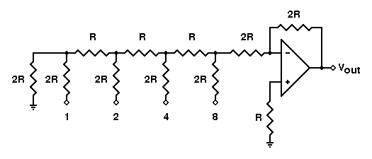
If you want an inverting D to A converter, the circuit shown above will work well. You may need to scale the output voltage, depending on your requirements.
Also, it is possible to have a bipolar D to A converter. If you apply the most significant bit to an analog inverter and use that output for the MSB position of the R-2R ladder, the binary number applied to the ladder will be handled as a two's-complement number, going both positive and negative.
| All pages on
www.play-hookey.com copyright © 1996, 2000-2003 by Ken Bigelow Please address queries and suggestions to: webmaster@play-hookey.com |