
Experiment 8 - Digital To Analog Conversion
| Home | Order | Let me know what you think -- e-mail |
There is frequently a need to convert digital information into a voltage or current. As noted in Data lines, bits, nibbles, bytes, words, binary and HEX, digital data changes in steps. Turning on or off a bit increases or decreases a digital quantity.
The following circuit, derived from the DAC0832 digital to analog converter (DAC) datasheet (see DAC0832.PDF), is one approach to making the conversion from stepwise digital information to a voltage. It's called an R 2R ladder and is part of the circuit used in the two DAC0832s on the board. R and Rfb are about 15K ohms, which makes 2R about 30K ohms. The actual values are not as important as the fact that the resistors are very closely matched to each other.
The "1" and "0" indicate the positions of MOSFET switches in the converter. A switch will connect to the "1" side if the corresponding bit is on, and to the "0" side if the bit is off. A switch connected to the "1" position will send a portion of Vref-derived current to Iout1, whereas a switch connected to the "0" position will send a portion of the current to Iout2.

To see how the R 2R ladder fits into the scheme of things, consider the following. The left side is a copy of one of the DAC0832 sections taken from the board's schematic. On the right is a simplified block diagram of the same thing, derived from the datasheet. Rfb is drawn in the manner shown to indicate it is internal to the DAC but can be accessed outside and be connected the Op-Amp:

Iout1 of the R 2R ladder is connected to the inverting input of the Op-Amp (see How To Read A Schematic for more on Op-Amps). Iout2 of the R 2R ladder is connected to the non-inverting input and to ground. One end of the internal Rfb feedback resistor is connected to the output of the external Op-Amp. The other end is internally connected to the R 2R ladder's Iout1 as shown above. Thus, it is connected from the output of the Op-Amp to the inverting input.
Recall that the Op-Amp will attempt to cancel any current through the inverting input. To do so, it will cause the current in the feedback resistor to be equal to the current in the inverting input resistor, but with an inverted polarity:
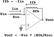
Since the currents are equal but opposite, they cancel each other out, resulting in 0 volts at the inverting input. Thus, the inverting input is at the same potential as ground. This generated ground equivalent is termed a virtual ground.
Here is what we know and what can be derived from it:
The current being canceled at the inverting input in the block diagram above
is Iout1. Thus,
Vout = Rfb * -Iout1. The datasheet says Vout = -(Iout1 *
Rfb), which is the same thing.
The board uses -5V from the computer as the reference voltage. Consider the case where the only the MSB is turned on (see Data lines, bits, nibbles, bytes, words, binary and HEX for a definition of MSB). The only resistor connected to Iout1 is the 2R resistor on the left end of the ladder. Since 2R = 30K and Rfb = 15K and Vref = -5V, we now have this:
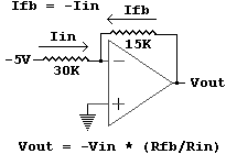
Now Vout = -(-5V) * (15K /30K) = 2.5V
Remember that the MSB has a weight of 128. The data sheet also says that
Vout = -(Vref * (Digital Input)10)/256 (the 10 means "base
10 number").
In the case of the MSB input,
Vout = -(-5V * 128)/256 =
2.5V, which agrees with the previous voltage calculations.
Getting rid of the double negatives and generalizing the numbers gives this:
Vout = (5 * DAvalue)/256, where DAvalue is the base 10 number output to the
converter.
A value of 1 will provide the voltage per step:
Vout = (5 * 1)/256 =
.01953125 volts
That would be true in a perfect world. There is however, no such thing as perfect in this world, despite the claims of some I have known regarding their own attributes. See the datasheet for a discussion of linearity.
The MSB case is relatively easy. Others require a bit more thought. They are also useful as exercises in a little circuit analysis. For example, consider the case where only bit 6 is high. The bit 6 MOSFET is switched to "1". All of the other bits will be connected to "0", which ends up at ground. The circuit will look like this, including the external Op-Amp and using the nominal resistor values from the datasheet:

The current through R1 does not influence the current referenced at the inverting input. Although one end is connected to the -5V reference, the other end simply goes to ground, so the current through R1 never even makes it to the inverting input.
All of the other resistors do contribute to the current at the inverting input and to the output of the amplifier. The current through R2 splits into two paths. One is through R3 which goes directly to the inverting input, and the other is through the network of R4 and all of the other resistors to ground. The method to determine their composite value is more easily seen if the R4 part of the drawing is reorganized. A careful study will show that only the drawing has changed. The circuit is the same:
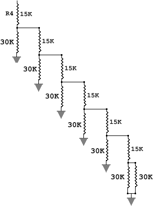
First consider the two 30K resistors on the bottom. Recalling the parallel
resistor equation from How To Read
A Schematic, A tip:
Rparallel = 1/(1/30K + 1/30K) = 15K ohms
The 15K parallel combination adds to the 15K above it since it is in series
with it. Again, from How To Read A
Schematic,
Rseries = 15K + 15K = 30K ohms
This 30K combination is in parallel with the 30K to the left of it, which produces 15K again which adds to the 15K above to produce 30K, and so on. The final value of the network is 30K. It would be a very good idea to print the picture, calculate the values and write them down as an exercise to clarify the process. There are other, more sophisticated ways to analyze the circuit, but this is straight forward and will do just fine for now.
The bit-6 circuit ends up looking like this after the resistor equivalents have been identified:

Since the inverting input is a virtual ground, the two 30Ks look like they
are paralleled, which means they look like 15K ohms. It is as if R1 is in series
with another 15K resistor. Recall from How To Read A Schematic
that the equivalent resistance in a series circuit is the sum of the resistors.
Thus, the total resistance seen by the reference is 30K ohms. The current
through R1 is I = -5/30K.
Half of it goes to ground through R2 and half
through R3, making
Iout1 = (-5/30K)/2 = -1/12K.
That makes Vout = -(15K * (-1/12K)) = 1.25 volts.
Also, since bit 6 has a
weight of 64 and Vout = (5 * DAvalue)/256 from above,
Vout = (5 * 64)/256 =
1.25 volts.
The two agree.
I'll leave it up to the reader to perform the analysis for other numbers. The next thing to be done here will be to see how the digital to analog converters on the board can provide analog information from digital information through software.
The digital to analog converters are accessed as offsets from the main port address for the board (see Address Lines and Ports and the Hardware Description for more on port locations). The offsets are shown below. Since the analog to digital converter needs eight bytes, each device is 8 bytes from the other:
| HEX Offset (add to port address) | Device On Board |
| 0 | Eight Channel Analog to Digital Converter |
| 0x08 | Digital to Analog Converter 1 |
| 0x10 | Digital to Analog Converter 2 |
| 0x18 | Analog to Digital Converter Ready Line And 3 Digital Inputs |
| 0x20 | Programmable Peripheral Interface |
| 0x28 | Spare Select Line |
| 0x30 | Spare Select Line |
| 0x38 | Spare Select Line |
The digital to analog converters are at port + 0x08 and port + 0x10.
The first thing to be done will be to slightly modify get_port() in the digital C module It currently returns nothing. It is modified to return the base port number:
// get the port -- this will grow into an auto-detect function in the future
unsigned get_port(void)
{
  base = 0x200; // all switches on -- change as required
  switch_port = base + 0x18;
  ppi_porta = base + 0x20;
  ppi_portb = base + 0x21;
  ppi_portc = base + 0x22;
  return base;

} // end get_port()
|
Now all we have to do is get the base port number, then add the offset for the required converter. Try this:
// experi8a.c

extern unsigned get_port(void);

main(void)
{
  int x;
  unsigned port,da1;

  if(!(port = get_port()))
  {
    printf("No board found\n");
    exit(0);
  }

  da1 = port + 8;

  printf("This sends 0 to 255 then 254 to 1 to DAC1\n");
  printf("as quickly as possible, then repeats.\n");
  printf("Both DACs have their grounds on pin 1 of header 1.\n");
  printf("DAC1's output is on pin 15 and DAC2's on pin 14.\n");
  printf("Press any key to begin, then press any key to end the test.\n\n");
  getch();

  disable();

  while(!kbhit())
  {
    for(x=0; x<256; x++)
    {
      outp(da1,x);
    }

    for(x=254; x>0; x--)
    {
      outp(da1,x);
    }
  }

  enable();
}

// end experi8a.c |
Compile experi8a.c and digi8a.c, then link them to produce experi8a.exe. Type experi8a <enter> to run it. The program continuously sends 0 through 255 then 254 through 1 to the first digital to analog converter. To send the same thing to the second converter in this and in the following programs, use something like da2 = port + 0x10; in the place of the one for da1 above, then outp(da2,x) rather than outp(da1,x).
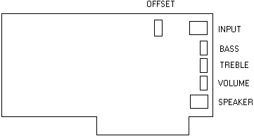
The problem with the above program is that you can't see the output without an oscilloscope because it runs too fast. It can be heard on most computers, though. Just connect a speaker or headphones (you will hear one channel with phones) to the board's speaker output and adjust the volume, bass and treble for taste:
The following uses the timer module to provide a pause between each step:
// experi8b.c

extern unsigned get_port(void);
extern int set_up_new_timer(double freq);
extern void wait(double seconds);
extern void restore_old_timer(void);

main(void)
{
  int x;
  unsigned port,da1;

  if(!(port = get_port()))
  {
    printf("No board found\n");
    exit(0);
  }

  da1 = port + 8;

  printf("This sends 0 to 255 then 254 to 1 to DAC1\n");
  printf("with a pause between each step then repeats.\n");
  printf("Both DACs have their grounds on pin 1 of header 1.\n");
  printf("DAC1's output is on pin 15 and DAC2's on pin 14.\n");
  printf("Press any key to begin, then press any key to end the test.\n\n");
  getch();

  set_up_new_timer(2000.0);

  while(!kbhit())
  {
    for(x=0; x<256; x++)
    {
      outp(da1,x);
      if(kbhit())
        break;
      wait(.025); // .025 second per step
    }

    for(x=254; x>0; x--)
    {
      outp(da1,x);
      if(kbhit())
        break;
      wait(.025); // .025 second per step
    }
  }

  restore_old_timer();
}

// end experi8b.c
|
Compile experi8b, digital and timer, then link them to produce experi8b.exe. You will be able to monitor its output on header 1 with a voltmeter rather than an oscilloscope when you then run experi8b. You can pick up an inexpensive voltmeter at Radio Shack and a lot of other places.
The above programs produce a somewhat distorted triangle wave:

The flat bottom can be seen on an oscilloscope while viewing the faster version. It's most likely a delay caused by the calling of the kbhit() routine. That's somewhat confirmed by the fact that it can't be seen when the slow version is viewed. A scope with a very slow trace is needed to prove the point, though (.5 second per division).
Probably more common in analysis than the triangle wave is the sine wave. The following shows the relationship of the sides of a triangle and associated trigonometric definitions. Note that it's common to abbreviate sine, cosine and tangent. A sine wave would be a plot of the sine of a changing angle A on a graph:
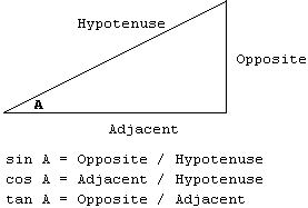
If you remember sine, cosine and tangent, in that order, and opposite, adjacent and hypotenuse, in that order, you can remember everything else:
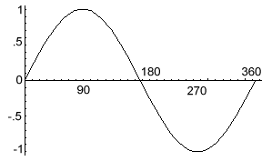
See Trigonometry and Right Triangles on the Zona Land site for more detailed information on trig functions. A graph of a sine wave is below. The sine of 0, 180 and 360 degrees is 0. The sine of 90 degrees is 1 and the sine of 270 degrees is -1.
Most C compilers use radian
calculations to find trigonometric values such as sine. Most people know that
the circumference of a circle is pi (about 3.141592654) times the diameter of
the circle:
C = pi * D
Half of the diameter is called the radius,
D
= 2r
so the circumference is also
C = pi * 2r
or, the same thing,
C = 2pi * r
Sweeping through an angle of one radian will trace an arc on a circle with the arc's segment length equal to the length of the circle's radius:
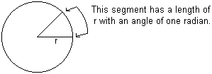
Since a radian moves through a segment equal to the radius, 2pi radians will trace the full circumference. There are 2pi radians in a circle. Here are a few radian to degree relationships:
|
Radians |
Degrees |
sin |
cos |
tan |
|
0 |
0 |
0 |
1 |
0 |
|
.5 pi |
90 |
1 |
0 |
undefined -- adjacent = 0 |
|
pi |
180 |
0 |
-1 |
0 |
|
1.5 pi |
270 |
-1 |
0 |
undefined -- adjacent = 0 |
|
2 pi |
360 |
0 |
1 |
0 |
See more detailed information about radians on the Zona Land site.
The purpose of this discussion is to introduce a method of generating tables that can be used to produce sine waves. The following program will generate a header file with a table. Several procedures are new and will be briefly covered here. See your compiler manual or help system for more detail.
First consider the FILE *out_file;
declaration. This is a structure declaration that sets up a pointer to a FILE
structure (see Experiment
3 and subsequent sections for a discussion of pointers). The pointer
is usually called a file pointer, and is commonly used to work with text files.
A file is opened using fopen(..). The
prototype is:
FILE *fopen(char *filename, char
*access);
The filename argument is a string holding the name of
the file. The access string argument tells the routine how to open the file.
Probably the most common ones are "r" for read, "w" for write and "a" for
appending to a file. Since the object here is to write to the file, "w" is used
below.
The flush() and close() calls make sure everything has been written to
the file and closes it.
There are some functions that will provide the angle in radians if the value of the trig type is known. The call to acos() in the program returns the angle for an angle that has a cosine of -1. That turns out to be pi from the table above, and 2 times the value will be 2pi. It's called pi2 here for reasons outlined in Putting It All Together - Controlling The Hardware With The Software.
The puts() routine was used in Experiment 3. A call to fputs() does about the same thing for a file; it puts pre-defined text in the file. Formatted text is handled here with fprintf(..). It works like printf(..), first described in Putting It Together, but with the addition of a file pointer.
The n variable is used in a for() loop (yup, Putting It Together) to count two cycles of a sine wave. A loop inside that one is used to run 0 through 2pi radians with a step of StepSize. In this case, StepSize is pi2/255. It can be changed for higher or lower frequencies.
Since the sine ranges from -1 to 1 and the digital to analog converter needs 0 to 255, some modification is needed. First 1 is added, which gives 0 to 2. Then the results of that are divided by that 2, giving 0 to 1. Finally, it's multiplied by 255 to give 0 to 255 (the call to sprintf with %1.0f causes a rounding of the floating point number).
The results are formated to fit on a page, then put in a file called slosin.h:
// makslo.c

#include <string.h>
#include <graphics.h>
#include <stdio.h>
#include <string.h>
#include <bios.h>
#include <dos.h>
#include <math.h>
#include <stdlib.h>

void main(void)
{
  int x,n;
  char temp[300];
  FILE *out_file;
  double StepSize,angle,pi2,sn,out,out2;

  pi2 = acos(-1.0) * 2.0;
  StepSize = pi2/255.0;

  out_file = fopen("slosin.h","w"); // store in slosin.h

  fputs("unsigned char sin_table[] = {",out_file);

  printf("unsigned char sin_table[] = {");

  for(n=0,x=0; n<2; n++)
  {
    for(angle=0.0; angle<=pi2; angle+=StepSize,x++)
    {
      if(x)
      {
        if(!(x % 10))
        {
          fputs("\n                            ,",out_file);
          printf("\n                            ,");
        }

        else
        {
          fputs(",",out_file);
          printf(",");
        }
      }

      sn = sin(angle);
      out = (sn + 1.0)/2.0;
      sprintf(temp,"%1.0f",255.0*out);
      out2 = atof(temp);
      fprintf(out_file,"%3d",(int)out2);
      printf("%3d",(int)out2);
    }
  }

  fprintf(out_file,"}; /* %d */\n",x);
  printf("}; /* %d */\n",x);
  fprintf(out_file,"\nint last = %d;\n",x);
  printf("last = %d\n",x);
  fprintf(out_file,"double StepSize = %f;\n",StepSize);
  printf("StepSize = %f\n",StepSize);
  printf("data send to slosin.h\n");
  fflush(out_file);
  fclose(out_file);
}

// makslo.c |
The table thus generated can be used to generate a sine wave using the following:
// experi8c.c

#include "slosin.h"

extern unsigned get_port(void);

main(void)
{
  int x;
  unsigned port,da1;

  if(!(port = get_port()))
  {
    printf("No board found\n");
    exit(0);
  }

  da1 = port + 8;  // da2 = port + 0x10;

  printf("This puts a slow sinwave on DAC1.\n");
  printf("Both DACs have their grounds on pin 1 of header 1.\n");
  printf("DAC1's output is on pin 15 and DAC2's on pin 14.\n");
  printf("Press any key to begin, then press any key to end the test.\n\n");
  getch();

  disable();

  while(!kbhit())
  {
    for(x=0; x<last; x++)
    {
      if(kbhit())
        exit(0);

      outp(da1,slo_sin_table[x]);
    }
  }
  outp(da1,0);
  enable();
}

// experi8c.c |
While this sine wave looks good on an oscilloscope, it might not be heard through the speaker because it's too low in frequency. A faster wave is needed. To get it, use a larger step size. The makefast program gets StepSize by dividing pi2 by 16 rather than 255 and sends the data to a file called fast_sin.h:
// makfast.c

#include <string.h>
#include <graphics.h>
#include <stdio.h>
#include <string.h>
#include <bios.h>
#include <dos.h>
#include <math.h>
#include <stdlib.h>

void main(void)
{
  int x,n;
  char temp[300];
  FILE *out_file;
  double StepSize,angle,pi2,sn,out,out2;

  pi2 = acos(-1.0) * 2.0;
  StepSize = pi2/16.0;

  out_file = fopen("fast_sin.h","w");

  fputs("unsigned char sin_table[] = {",out_file);

  printf("unsigned char sin_table[] = {");

  for(n=0,x=0; n<10; n++)
  {
    for(angle=0.0; angle<=pi2; angle+=StepSize,x++)
    {
      if(x)
      {
        if(!(x % 10))
        {
          fputs("\n                            ,",out_file);
          printf("\n                            ,");
        }

        else
        {
          fputs(",",out_file);
          printf(",");
        }
      }
      sn = sin(angle);
      out = (sn + 1.0)/2.0;
      sprintf(temp,"%1.0f",255.0*out);
      out2 = atof(temp);
      fprintf(out_file,"%3d",(int)out2);
      printf("%3d",(int)out2);
    }
  }

  fprintf(out_file,"}; /* %d */\n",x);
  printf("}; /* %d */\n",x);
  fprintf(out_file,"\nint last = %d;\n",x);
  printf("last = %d\n",x);
  fprintf(out_file,"double StepSize = %f;\n",StepSize);
  printf("StepSize = %f\n",StepSize);
  printf("data send to fast_sin.h\n");
  fflush(out_file);
  fclose(out_file);
}

// makfast.c |
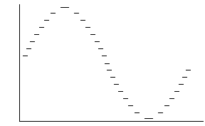
Now run it using experi8d.c below. You should be able to hear it on the speaker. It won't sound too clean because of the step size. You should be able to see the steps on an oscilloscope:
// experi8d.c

#include "fast_sin.h"

extern unsigned get_port(void);

main(void)
{
  int x;
  unsigned port,da1;

  if(!(port = get_port()))
  {
    printf("No board found\n");
    exit(0);
  }

  da1 = port + 8;

  printf("This puts a faster sinwave on DAC1.\n");
  printf("Both DACs have their grounds on pin 1 of header 1.\n");
  printf("DAC1's output is on pin 15 and DAC2's on pin 14.\n");
  printf("Press any key to begin, then press any key to end the test.\n\n");
  getch();

  disable();

  while(!kbhit())
  {
    for(x=0; x<last; x++)
    {
      if(kbhit())
        exit(0);

      outp(da1,sin_table[x]);
    }
  }
  outp(da1,0);
  enable();
}

// experi8d.c |
While the sound can be heard, it is distorted because of the step size. This is what it looks like on a scope:
A faster means of delivering the signal is needed in order to get a reasonably smooth signal out fast enough to be audible (unless your computer is much faster than my old test computer). That will be covered in another section since it requires a discussion of assembly code.
Meanwhile, you might want to download the free software on my Super Start site. It can use the
board, and the zip file includes source with the assembly code. As a bonus,
Super Start is designed to help very young children get the core knowledge
needed for a good beginning in education.
Previous:
Next: Experiment 9 - Analog To Digital
Conversion
Problems, comments, ideas?
Please e-mail me
Copyright © 2001, Joe D. Reeder. All Rights Reserved.